Hello, this is Ryuta Hamamoto from TIMEWELL.
On September 30 and October 1, we showed ZEROCK's drawing AI at AI Hakurankai Fukuoka 2026, an AI trade show held at the Hakata International Exhibition & Conference Center in Fukuoka, Japan. The people who came to talk to us were not only machinery manufacturers. There were equipment makers, construction companies, building contractors, and piping contractors. Different trades, but the opening question was nearly always the same: can you turn our 2D drawings into 3D?
The thing is, "3D" means different things in each of those trades. A machinery maker wants a STEP file to hand to a customer. A piping contractor wants to see, before work starts, whether pipes, ducts, and beams will collide above the ceiling. A building contractor wants to start planning a renovation from as-built drawings that only exist on paper. The drawings differ, the use of the 3D model differs, and so does how much you can safely hand to AI. Yet nearly everything you find online assumes you are converting a machined part. To be honest, so did our own earlier articles.
So this piece goes trade by trade: machinery makers, equipment makers, civil contractors, building contractors, and piping contractors. For each, where the drawings cause trouble, how far AI can go, and what a person still needs to check. I backed up each trade's situation with primary sources, mostly standards and surveys published by Japan's Ministry of Land, Infrastructure, Transport and Tourism (MLIT) and by industry bodies. If you want a rough read on how ready your company is for AI first, the AI readiness check takes a few minutes.
Here is the short version. What changes from trade to trade is what the drawing leaves out. A machined part's three-view drawing usually closes all its dimensions. A piping plan often says nothing about height. A building drawing cannot give you the attribute data that BIM carries. AI is good at two things here: building a first-draft shape from the lines and dimensions that are on the drawing, and turning old paper or PDF drawings back into DXF. The parts the AI had to assume, such as missing heights or depths, and any judgment against construction or estimating rules, stay with a person. Draw that line for your trade up front, and 3D conversion stops being the thing you tried once and gave up on.
| Trade | Typical drawings | Why they want 3D | Easy to hand to AI | A person checks |
|---|---|---|---|---|
| Machinery makers | Part drawings, assembly drawings, paper drawings of old models | STEP files for customers, modifying installed machines | STEP or STL from three-view drawings, paper to DXF, draft estimates | Free-form surfaces, how parts fit together, tolerances |
| Equipment makers | Outline drawings, installation drawings | Customer layout studies, envelope models for BIM | Envelope models from outline drawings | Connection locations and sizes, service clearances, attribute data |
| Civil contractors | Issued drawings (PDF), drawings of existing structures | Construction planning, sharing shapes with partners | Shapes of single structures or members, old drawings to DXF | Terrain, alignments, construction sequence |
| Building contractors | Plans, elevations, sections, paper as-builts | Renovation planning, explaining to owners | Old drawings to DXF, first-draft building shapes | BIM attributes, code compliance |
| Piping contractors | Piping plans, MEP drawings, shop drawings | Coordination, quantity takeoff | 3D from plans, material for seeing clashes in 3D | Assumed heights, risers and drops, drain slopes, takeoff quantities |
Why "3D conversion" means something different in each trade
Every drawing rests on agreed shortcuts. In mechanical drafting, the three views (front, top, and side) are drawn so that the part's dimensions close completely. If the three views agree, everything the AI needs to infer the shape is already on the sheet. I covered how a STEP file gets built from a 2D drawing in the practical guide to 2D-to-3D STEP conversion.
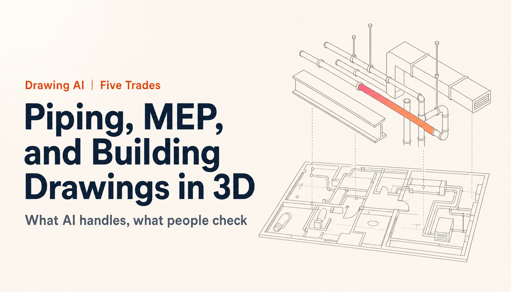
MEP and piping drawings work differently. Pipes are drawn as single lines, and height is usually given by an annotation such as "FL+2,800" (2,800 mm above the finished floor) or in a separate section. There is a further wrinkle. In a Q&A that MLIT's Government Buildings Department published in September 2026, the ministry notes that its reference material for preparing building services design documents says stacked pipes "may be drawn side by side"1. In other words, when pipes run one above the other, the drawing may spread them out horizontally to keep it readable. So on a piping drawing, the position on paper can be deliberately different from the real position. Build a model straight from that drawing and what do you get? The pipes in their shifted positions, in 3D.
Building drawings are different again. Plans, elevations, and sections together describe the building, while BIM adds attribute data to the same model: room names, floor areas, component specifications and performance. IFC, the open file format for BIM, is an international standard, ISO 16739-12. The STEP files an AI produces from drawings follow ISO 10303, the standard for exchanging 3D CAD geometry3, and STL approximates surfaces with triangles. Neither carries attribute data.
Let me be specific about what our ZEROCK drawing AI can and cannot do. It reads DXF, PDF, PNG, JPG, WebP, TIFF, STEP, IGES, and STL; DWG files should be exported to DXF first. It outputs STEP, STL, and DXF, and estimates come out in Excel. It has three weak spots. Depth or height that cannot be read from the drawing becomes an assumption. Free-form surfaces are hard for it. And conversion from PDF is not a mechanical auto-trace, so the result needs checking. Accuracy depends heavily on the state of the drawing, which is why I am not quoting accuracy figures here. Whether it suits your trade mostly comes down to where those three weak spots land on your drawings.
Machinery and equipment makers: old drawings and "send it in 3D"
The two manufacturing trades come to 3D for similar reasons. Customers ask for 3D data, the company only has 2D, and the older the drawing, the more likely it survives only on paper or as a scanned PDF. What differs is how much detail the customer actually needs.
Machinery makers: the hard part is old paper drawings and assemblies, not single parts
Building a STEP file from a machined part's three views is something AI does well. For parts made of prisms, cylinders, holes, and fillets, shape inference is stable as long as the views agree. The drawings that really cause trouble for machinery makers sit outside that.
One is the paper drawing of an old model. When a request comes in to modify or service a machine delivered decades ago, all you may have are blueprints or scanned PDFs. The person who drew them has retired, and fewer people in the company can read their habits. Japan's 2026 White Paper on Manufacturing Industries reports that manufacturing employment slipped to 10.33 million in 2025, and that the employee surplus/shortage index for small and medium manufacturers (the share reporting a surplus minus the share reporting a shortage) stood at minus 17.94. More than 60% of establishments named "not enough people to teach" as a problem in developing their staff4. I would not expect the shortage of people who can read old drawings to ease soon.
The other is the assembly drawing. Unlike a part drawing, it shows how parts sit and fit together, and it does not necessarily give every dimension of every part. AI can produce a first-draft envelope of an assembly, but whether each part sits in the right place has to be checked by a person against the part drawings. Free-form shapes such as cast housings and molded covers also still need a human hand.
And the customers? They are slowly moving to drawings built around 3D. The Japan Electronics and Information Technology Industries Association (JEITA) publishes a standard (ET-5102) and guidelines for "3DA models," which put dimensions and tolerances directly on the 3D model5. If the supplier stays 2D, someone spends half a day rebuilding a model every time a STEP file is requested. Hand the first draft, the paper-to-DXF work, and the draft estimate to AI, and let people spend their time verifying dimensions, tolerances, and fit. I think that split is the realistic one. For the estimating side, see how to automate quotes from drawings.
Equipment makers: customers want the envelope and the connections
For companies that build boilers, chillers, pumps, air handlers, or production equipment, the request shifts a little. What the customer usually wants is not a model that reproduces the internals but an envelope model they can drop into a building or factory layout.
The driver is BIM in the building sector. Japan's BIM Library Consortium (BLCJ) published version 2.1 of its BIM object standard in February 2026. Its scope covers mechanical equipment including boilers, chillers, cooling towers, pumps, fans, air handling units, energy recovery ventilators, water heaters, water storage tanks, and valves, and the consortium reports ongoing work to spread the standard among manufacturers6. When designers and general contractors assemble a building in BIM, they naturally want 3D models of the equipment that goes in it.
Current products may already have models. Older models and built-to-order units often have nothing but a 2D outline drawing. That is where AI earns its keep: generate a STEP or STL envelope from the outline drawing's three views, and you have a first draft that works for a customer's layout study.
What a person needs to check is the location and size of the piping and power connections, the clearance needed for inspection and maintenance, and attribute data such as model numbers and performance. STEP and STL carry geometry only, so turning the shape into a usable BIM object is a separate step. One more thing: I think envelope models are easier for the receiving side to work with when they are not over-detailed. MLIT's own government building projects set the level of detail for ducts and pipes at the design stage to "what is needed for clash checking" and avoid asking for excessive modeling1. The people assembling the building in BIM care about the envelope, the connections, and the service space far more than about what is inside the unit.
Struggling with AI adoption?
We have prepared materials covering ZEROCK case studies and implementation methods.
Civil and building contractors: working on projects that do not run on BIM
Construction in Japan has a strong policy push toward BIM. There is still a real gap, though, between that push and the drawings sitting on most desks. AI-based 2D-to-3D conversion makes the most sense when you see it as a way to bridge that gap.
Civil contractors: BIM/CIM is the rule, but 2D is still on hand
Since fiscal 2023, MLIT has applied BIM/CIM as the rule to all of its directly managed civil engineering contracts, excluding small ones7. Its "i-Construction 2.0" plan, adopted in April 2024, aims to cut labor on construction sites by at least 30% by fiscal 2040, which is a 1.5-fold productivity gain8. The reason is a shrinking workforce. Japan's construction industry employed 4.77 million people in 2024, down sharply from a peak of 6.85 million in 1997. Workers aged 55 and over make up 36.7%, and those 29 and under only 11.7%9. Since April 2024, construction has also been subject to legal caps on overtime10.
Even so, not every drawing arrives in 3D. The construction companies that talked to us at the show also wanted to turn 2D drawings they already had into 3D. A survey of the building sector, not civil work, found that only 43.4% of companies answering as general contractors had adopted BIM, meaning more than half had not11. Count the exchanges with subcontractors and partners, and the share of work running on 2D is surely higher.
What AI handles well here is getting a 3D view of a single structure or member, and converting paper or scanned drawings of existing structures back into DXF. Retaining walls and box culverts, whose dimensions close within the drawing, are likely good candidates. Terrain and road alignments, where curves and free-form surfaces dominate, belong to survey data and dedicated BIM/CIM software and are poor candidates for AI conversion from drawings. Construction sequencing and temporary works planning stay with people. Rather than thinking of AI conversion as a BIM/CIM substitute, I would treat it as a tool for making visible the drawings that BIM/CIM does not cover.
Building contractors: BIM review has started, but half the industry still works in 2D
On April 1, 2026, Japan started accepting BIM-based drawing review for building permits. Applicants submit PDF drawings exported from BIM along with IFC data, and reviewers can skip part of the cross-checking between drawings. The IFC data is not itself reviewed; it serves as a reference for understanding the shape. A further step, "BIM data review," which uses the IFC data directly in the review, is planned for spring 202912.
Meanwhile, an MLIT survey of members of 13 building-sector associations in January 2025 (1,738 responses) found that 49.7% of companies had adopted BIM11. Company size makes a big difference: 33.6% for firms with one or two employees, 31.9% for 31 to 50, 70.3% for 101 to 300, and 93.8% for 1,001 to 2,00011. Among the reasons given for not adopting it (multiple answers allowed), 69.0% said they could work without problems in CAD, 68.3% said clients were not asking for BIM, and 55.8% said switching would be a heavy burden until staff got up to speed11. For small builders and design offices, a full move to BIM is still some way off, and the numbers show it.
Where 2D-to-3D conversion helps this group is in renovation and extension work, for example. Even for a building whose only as-builts are on paper, converting the drawings back to DXF and turning the building into a first-draft 3D shape makes it easier to explain plans to the owner and scope the work.
One thing must not get mixed up here. The STEP and STL files AI produces are not IFC and carry no attributes such as room names, areas, or specifications, so they cannot be submitted for BIM drawing review. Code questions such as daylighting and egress are, of course, still a person's job. I would keep two decisions separate: whether to move the business to BIM, and the day-to-day need to see a 2D drawing in 3D. The first is a multi-year investment. The second is getting ready for tomorrow's meeting.
Piping contractors: dealing with the height the plan never shows
Of the five trades, piping needs the most care. ZEROCK can read piping and MEP drawings and turn them into 3D, but piping drawings leave out more information than any of the others.
Piping work starts with shop drawings. Japan's standard specification for public building mechanical work requires contractors to prepare shop drawings before construction, get them approved by the supervising engineer, and coordinate fit and interfaces with the other trades while preparing them13. Above the ceiling and in plant rooms, ductwork, plumbing, cable trays, beams, and equipment all compete for limited space. On many sites, isn't this still checked by overlaying plans and sections in someone's head?
Convert a piping plan to 3D with AI and you can see those clashes in three dimensions. The catch is height. Wherever the drawing does not give a height, the AI fills one in by assumption. ZEROCK's own product notes say as much: depth that the drawing does not give is assumed. As I mentioned earlier, on drawings where stacked pipes are spread out side by side, even the plan position differs from reality. Drain lines slope, so their height changes along each run. Have a person check that the model's heights match the annotations and sections.
Height matters for quantity takeoff too. Japan's public building MEP quantity standard counts piping as straight lengths, measuring bends to the point where the extended straight lines meet. It then says that branches off a main and connections to plumbing fixtures are counted as lengths that "include risers and drops"14. On a plan, a riser or drop is just a point, so its length cannot be known until the heights are fixed. ZEROCK can produce a draft estimate in Excel from a drawing, but whether that works for piping takeoff as-is depends on how your drawings are drawn and how your company counts. At a minimum, plan on a person checking riser and drop lengths and the counts of fittings and valves against the standard and your own takeoff rules.
Why would I still push piping contractors toward 3D? Less for how it looks than because it brings out every spot where the shape cannot exist until someone decides a height. On a 2D plan you can read right past "who decided this height?" In 3D, it is right in front of you. Use the model to list the undecided heights before drawing the shop drawings, and settle them with the designer and the other trades. To me, that is where 3D conversion of piping drawings pays off most.
Deciding what AI handles and what people check, across every trade
The five trades have very different drawings, but the checking process can share one frame. Before you start, try writing these down in order.
- Prepare the inputs. Export DWG files to DXF, and scan paper drawings as cleanly as you can. The state of the drawing shows up directly in the result.
- Write down what the drawing does not say. Heights for piping, floor-to-floor and ceiling heights for buildings, hidden geometry and fit for machinery. This is where you see what the AI will have to assume.
- Spot-check the 3D draft against a few reference dimensions. You do not need to re-measure everything, but always check the dimensions that drive clashes or fit.
- Correct the draft estimate with your own unit rates and estimating rules. The Excel output is a starting point, not an answer.
- Decide how drawings may be handled. Confirm in your contracts whether drawings lent by customers, or covered by a nondisclosure agreement, may be put into an outside service.
That last item comes before any technology. I wrote about checking revisions and return obligations on drawings you receive in the 12 things to check when you receive a customer's drawing, and about what to decide before giving drawings to generative AI in drawings, AI, and the trade secret boundary.
In this flow, AI shortens three jobs: turning paper drawings back into DXF, building the first-draft shape, and drafting the estimate. Listing what the drawing leaves out (step 2), deciding how drawings may be handled (step 5), and the final calls in steps 3 and 4 stay with people. Settle that division at the start and nobody on site has to wonder how far to trust what the AI produced. In my view, rollouts go wrong less because of the AI's capability than because they start without drawing this line.
Try it on your own drawings for 14 days
In the end, you will not know how well this fits your trade until you try it on your own drawings. Two piping drawings can give different results depending on how they are annotated and what state they are in. Trying one of your drawings will tell you more than comparing brochures.
ZEROCK's drawing AI is included in every plan and in the free trial. The trial lasts 14 days, needs no credit card, and does not bill you automatically when it ends. It comes with 500 credits, and converting one drawing to 3D typically takes 300 to 500, so start with the one drawing that gives you the most trouble. For a machinery maker, a part drawing a customer wants in STEP. For an equipment maker, the outline drawing of an older product someone asked for in 3D. For a civil contractor, part of a drawing of an existing structure. For a building contractor, the paper as-builts of a building about to be renovated. For a piping contractor, a tight ceiling-void piping drawing. A drawing like that will give you a quick sense of how far it goes for you.
You can sign up for the ZEROCK free trial here. The ZEROCK page has the overall picture, and ZEROCK for Makers covers manufacturing use. If you would like to talk through whether it fits the drawings in your trade first, get in touch with the ZEROCK team.
Summary
- What changes by trade is what the drawing leaves out. Machined parts usually close their dimensions; piping leaves out heights; building drawings leave out BIM attributes.
- For machinery makers, the hard cases are paper drawings of old models and assembly drawings. Give AI the STEP draft, the DXF conversion, and the draft estimate; keep fit and tolerances with people.
- Equipment makers are asked for light models with the right envelope and connections. Adding BIM attributes is a separate job.
- Civil work runs on BIM/CIM as the rule, yet 2D drawings remain on hand. Terrain and alignments are out of scope; single structures are a better fit.
- In building, BIM drawing review began in April 2026, but BIM adoption is 49.7% overall and 33.6% for firms with one or two employees. STEP and STL are not IFC and cannot be submitted.
- In piping, the AI fills in the heights a plan does not show. People check risers, drops, and slopes, and the 3D model becomes a tool for listing the heights nobody has decided yet.
Talking with people from so many trades at the show convinced me that the demand to turn 2D drawings into 3D reaches well beyond machined parts. Meeting it, though, starts with putting into words what your drawings do not say. Pick the one drawing that causes your team the most trouble, list what is missing from it, and start there.
References
Related Articles
- The practical guide to 2D-to-3D STEP conversion
- Converting drawing PDFs to DXF
- How to automate quotes from drawings
- The 12 things to check when you receive a customer's drawing
Footnotes
-
MLIT Government Buildings Department, Q&A on Eizen BIM models and templates (September 16, 2026 edition), Nos. 12 and 13 (Japanese) ↩ ↩2
-
ISO 10303 (STEP: Standard for the Exchange of Product model data) ↩
-
Ministry of Health, Labour and Welfare, 2026 White Paper on Manufacturing Industries (Monodzukuri), summary (May 2026) (Japanese) ↩ ↩2
-
JEITA Global CAD Design Promotion Committee, 3DA model standards and guidelines (Japanese) ↩
-
BIM Library Consortium (BLCJ), FY2025 activity report (final), material 3 for the 16th Building BIM Promotion Council (March 24, 2026) (Japanese) ↩
-
MLIT, White Paper on Land, Infrastructure, Transport and Tourism in Japan 2025, Part II, Chapter 9, Section 4 (BIM/CIM) (Japanese) ↩
-
MLIT press release, "i-Construction 2.0 adopted" (April 16, 2024) (Japanese) ↩
-
MLIT, "MLIT initiatives," material 1-3 for a Regulatory Reform Promotion Council working group (May 8, 2025), based on the Labour Force Survey by the Ministry of Internal Affairs and Communications (Japanese) ↩
-
Ministry of Health, Labour and Welfare, "Overtime caps now apply to the construction industry" (Japanese) ↩
-
MLIT, Survey on BIM use and adoption in the building sector, final detailed results (January 2025) (Japanese) ↩ ↩2 ↩3 ↩4
-
MLIT, briefing materials on the BIM drawing review system (December 2025) (Japanese) ↩
-
MLIT Government Buildings Department, Standard Specifications for Public Building Construction (Mechanical Works), 2025 edition, 1.2.3 Shop drawings (Japanese) ↩
-
MLIT, Quantity Estimation Standard for Public Building MEP Works (2025 revision), Part 4, Chapter 1, Section 1: Piping (Japanese) ↩